Passive infra-red (PIR)
 Figure 1: HW-416 PIR sensor
A PIR sensor detects changes in incoming infra-red (IR) radiation and outputs a signal. They are typically tuned to the frequency of IR that corresponds to normal human body temperature and so they make good motion detectors. They are not completely dependent on live people or creatures, though, since any movement will cause changes in the ambient IR field through occlusion, reflection, etc.
Most cheap PIR sensors are designed to run on 5V. However, their internal electronics actually runs at 3V. If you need to power an IR sensor with 3V, as you would when using an Argon, there is a simple fix.
Hardware setup for 5V
The setup is very simple: the output from the sensor is simply connected to a digital pin. In Figure 2, we are using D02.
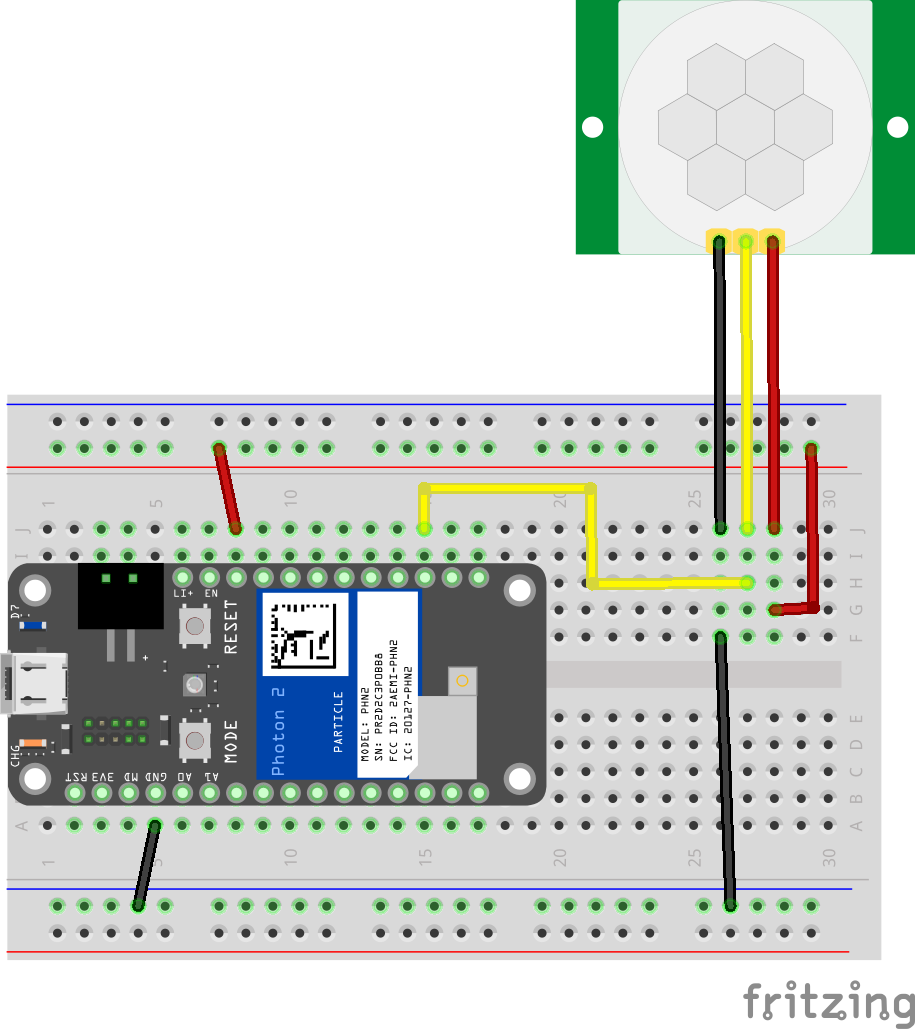 Figure 2: Breadboard layout for 5V
Hardware setup for 3.3V
As well as the three main connection pins, the HW-416 has another set of pins used to configure the behaviour of the device as shown in Figure 3.
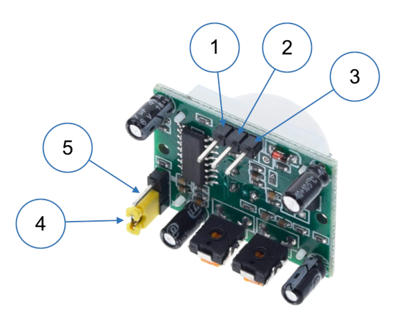 Figure 3: PIR sensor connections
(1): 5V in
(2): Output
(3): Ground
(4): Configuration pins shown with two of them connected by a jumper
(5): The configuration pin shown unconnected here can be used as a 3.3V power input
As noted above, the free configuration pin can be used for 3.3V power input, but please note that it has to be the pin shown in Figure 3. Trying to use the other two configuration pins in this way will not work.
Why can we do this? This video explains.
This means that the breadboard layout is slightly different. In Figure 4, power is
supplied by the Argon's 3.3V pin rather than the VBUS pin in Figure 3. Note too
that when using 3.3V, the default power input pin on the sensor is not connected to
anything.
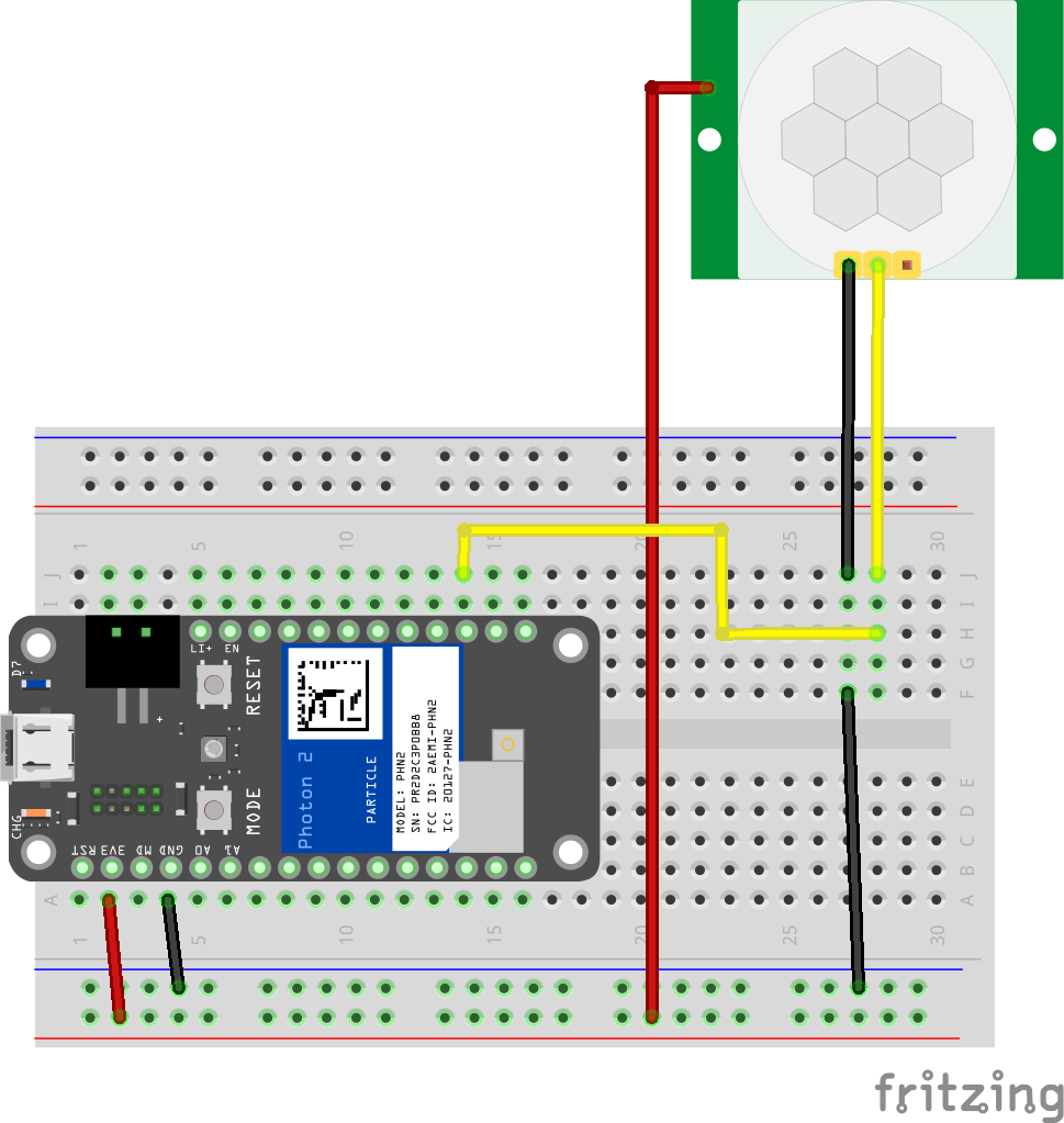 Figure 4: Breadboard layout for 3.3V
Software
The sketch below will work with either of the layouts shown above.
1 2 3 4 5 6 7 8 9 10 11 12 13 14 15 16 17 18 19 20 21 22 23 24 25 26 27 28 | |
If you need to trigger an action as soon as motion is detected, you will need to use interrupts. The sketch below provides and example that you can modify for your own purposes.
1 2 3 4 5 6 7 8 9 10 11 12 13 14 15 16 17 18 19 20 21 22 23 24 25 26 27 28 29 30 31 32 33 | |
Notes
Line 11: The interrupt is triggered by a rising signal on the PIR pin.
Line 17: The variable
motionFlagis set by the interrupt subroutine.Lines 20 & 22:
millis()gives the current time in milliseconds since the sketch started. These two lines generate a 500ms delay.Line 27: The main processing includes a 1s delay. The interrupt subroutine can set the
motionFlagduring the delay.
Notice that the interrupt subroutine ony sets the value of a variable. It is best to keep subroutines short and to do other processing in the main program loop.
 Fritzing part