Objects and relations
The current standard for application development is the object-oriented model in which data and processing are tightly connected. A software application for use in a bank, for example, might represent a customer as a software object with certain attributes and also certain behaviours. When a bank teller is responding to a customer the application represents that person as a software object which includes the customer name, account number, current balance, latest statement details and so on. If the customer wishes to make a deposit, that could be represented as a behaviour of the the customer object. Other behaviours would represent other actions such as make withdrawal and request overdraft.
Representing things as software objects makes the application structure easier to understand. Because the behaviour of the software object is defined along with its attributes, application development is simplified because object definitions can be re-used without any need to re-implement the same behaviours in the new application.
Both objects and relations are used to represent things in the problem domain. However, there are some major differences in the way they do that. Firstly, objects can be complex. In the example of the bank application, the customer object includes several recent transactions as part of the statement data. This is a one to many relationship which would have to be disaggregated in a relational database with the personal details stored in one table and the statement records in another.
Another difference is that the object model allows for relationships between object types (or classes to use the appropriate term) which have no direct counterpart in a relational structure. We have already seen one of these in week 4 which offered three different ways of representing the specialisation/generalisation relationship. The table below summarises some of the other main differences.
| Objects | Relations |
|---|---|
| Objects comprise data and procedures | Relations define data and relationships |
| Object model elaborated using generalisation, inheritance etc. | ER model elaborated using normalisation |
| Application is made up of objects | Database is separate from the application |
| Objects "die" when application terminates | Relations comprise persistent storage of data |
| Attributes can be complex types or other classes | Attributes comprise elementary data types |
Persistence
A major issue for object-oriented application programs is that although some objects are transient and can be discarded when the application terminates, other objects must persist from one use of the application to the next. In the bank example, it is clearly important that the customer details are retained even if the system is switched off. Pairing a database with the object-oriented application can provide a solution to the persistence problem, but only if the differences between the two models can be resolved.
Relational databases are not the only way that data can be carried over from one invocation of an application to the next. Ordinary files could also be used, but there are a number of problems with this when large amounts of data are involved, and the advantages of database systems were covered in week 2. For small amounts of data, however, they can be appropriate.
A further option is to use a so-called object database which is capable of storing complex structures. A number of such systems exist, and details of several can be found at odbms along with a range of other related materials. However, the application programmer may be required to use an existing relational database, or may prefer a relational database on performance grounds.
The choice of a persistence architecture is therefore part of the overall design of the application.
Some relational database platforms such as Oracle provide special features for handling object-like structures in a transparent way. Data in these object relational systems is still stored in a relational schema, however, and behaviours must be implemented using the native procedural extensions to SQL. This can limit the portability of objects from one system to another.
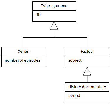
UML class diagrams
UML class diagrams extend the basic entity-relationship to include specialisation/generalisation and inheritance. This is done as shown below with a large triangular arrowhead pointing towards the superclass and a branching relationship line leading to the subclasses.
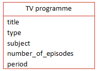
Single table solutionBecause relational databases cannot handle this type of relationship directly, equivalent structures have to be used, and there are different ways that this can be done. The first option is to use a single table for all of the classes in a hierarchy, typically including a type column to differentiate them as shown on the right. The main disadvantage of this solution is that any record that corresponds to an object high up in the hierarchy will contain many null values. For example, a feature film would have a title, but none of the other columns shown here would have a value.
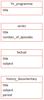
The second solution is to represent each member of the class hierarchy by its own table as shown below. The main disadvantage here is that similar entities (ie TV programmes) are held in different tables. Thus the generalisation is lost, and any general query - on title, for example - would be very complicated to perform. A possible solution to this lies in creating views which reproduce the different hierarchical levels.
1 2 3 4 5 6 7 8 9 10 11 12 13 | |
Object mapping
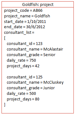
The structure of a relational database capable of holding the data for a set of persistent objects can be derived from the structure of the objects themselves. Using the same example as we did on week 6 when we looked at normalisation, a project could be represented as shown below. The consultants who work on the project are represented as a collection of nested objects.
A set of mapping rules can be used to transform the object structure into the equivalent relational structure:
-
Classes with simple data structure become tables
-
Object IDs become primary keys
-
Where classes contain another class as an attribute create a table for the embedded class
-
For collections create two tables, one for the objects in the collection, the other to hold object IDs of the containing objects and the contained objects - this is equivalent to creating a link table for a many-to-many relationship
-
One-to-many associations can be treated like collections
-
Many-to-many associations become two separate tables for the objects and a table to hold pairs of object IDs
-
One-to-one associations are implemented as foreign-key attributes - each class gains an extra attribute for the object ID of the other
-
Inheritance (generalisation/specialisation) can be represented in three different ways, each of which has its disadvantages:
-
only implement the superclass as a table including all subclass attributes
- only implement the subclasses as tables, duplicating superclass attributes in each
- implement superclass and subclasses as tables with shared primary keys
In the project case, we will end up with the same structure as we did using normalisation.
To simplify the process of addressing relational structures from an object-oriented program, several frameworks can be used including JDO, Hibernate and LINQ