Parallel relationships
Parallel relationships occur when there are two or more relationships between two entity types. Thinking about the example of PLAYERS and their TEAMS, we have seen that one PLAYER can captain one TEAM. Another more obvious relationship between these two entities is that each PLAYER plays for one TEAM. We can show this on an ER diagram like this:
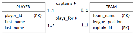
Each relationships is shown separately. Notice that the plays_for relationship is shown from the PLAYER perspective. Usually it is best to represent relationships from the perspective of the entity at the 'one' end of the relationship. In this case, the version shown is a more natural expression.
The multiplicity label at the PLAYER end of the plays_for relationship shows that a TEAM must have at least one PLAYER, and the relationship is mandatory in both directions.
The foreign key for the captains relationship is already shown in the TEAM table. The plays_for relationship must also be represented by a pair of keys. Because the TEAM is at the 'one' end of the relationship, we must add the TEAM primary key as a foreign key to the PLAYER table as shown below.
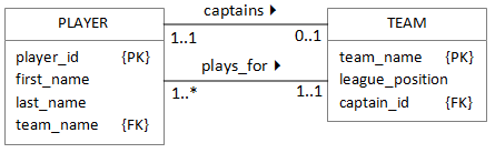
Now we have a complicated situation in which the primary key of each table is used a foreign key in the other. This only happens for parallel relationships - two foreign keys means two relationships. Notice that because we have used the name captain_id for the foreign key in the TEAM table, it is easier to work out which keys belong to which relationship.
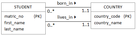
Using another example of a university database that stores details of students, we can see that the university needs some information about the country the student is from in order to calculate fees correctly. However, a STUDENT may have been born in one COUNTRY, but live in another. These are two different relationships between STUDENTS and COUNTRIES. Where do the foreign keys go?
The multiplicity labels tell us that both relationships are *:1 and both are in the same direction. That means that for each one, we take the primary key for the COUNTRY table and include it as a foreign key in the STUDENT table. This is perfectly legal, and we already know that we can give the foreign key column a different name. The result would be something like this:
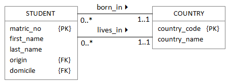
Remember: each foreign key represents a different relationship.
Recursive relationships
In some cases, an entity may be related to another entity of the same type. The classic example of this is in a company where some employees are managers and are therefore responsible for other employees. The ER diagram would look like this:
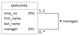
The manager column contains the emp_no for an EMPLOYEE's manager, so if Erik Eriksson is the manager of a team of three other employees, the data might look like this:
| emp_no | first_name | last_name | manager |
|---|---|---|---|
| 234 | Erik | Eriksson | |
| 432 | Donald | McDonald | 234 |
| 524 | Ivan | Ivanovich | 234 |
| 312 | Connor | o'Connor | 234 |
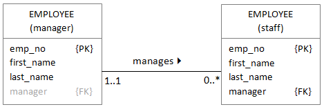
Recursive relationships can be difficult to understand. Sometimes it can help to imagine two copies of the table just while you are mapping the entities into database tables as shown below. It would be wrong to leave the extra copy in the ER diagram, though.
Specialisation / generalisation
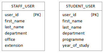
Often, a category of entities can be broken down into smaller categories. Each of the smaller categories shares some attributes, but also have differences in other attributes. If you are familiar with object orientation, this idea should be familiar. Imagine, for example, a database used by a university IT service department to store user details. All users will share some attributes such as first name, last name and department/school; however some of them will be staff and some will be students. Each of those sub-types has additional specific attributes. You can represent this in an enhanced ER diagram like this:
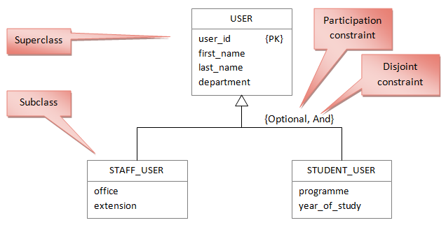
The diagram shows the USER superclass split into two subclasses, STAFF_USER and STUDENT_USER. Notice the large white arrow that indicates the specialisation/generalisation relationship and the two constraints.
The participation constraint takes one of two values. Mandatory would mean that every USER entity must be either a STAFF_USER or a STUDENT_USER. The value optional used here shows that there may be other types of USER (guests, for example) who are neither staff nor student.
The disjoint constraint also takes one of two values. Or would mean that an entity must be in only one subclass; the value and in the diagram shows that a USER can be both a STAFF_USER and a STUDENT_USER (if for example, a lecturer is taking a postgraduate course).
This level of detail is possible when modelling real entities and their relationships, but you still need to decide how to map them into database tables. You have three options, and your choice will depend on the application you are designing. Only the first method is a true reflection of the superclasses and subclasses. If either of the other methods is chosen as the most suitable then the specialisation/generalisation relationship should be removed from the model.
1. One relation for the superclass and one relation for each subclass
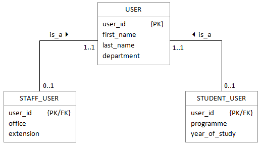
The primary key of the superclass is mapped into each subclass and becomes the subclasses primary key. This represents most closely the Enhanced ER model. However it can cause efficiency problems as there needs to be a lot of joins if the additional information is often needed for all staff.
2. One relation for each subclass
All attributes are mapped into each subclass. It is equivalent to having three separate entity types and no superclass.
3. One relation for the superclass
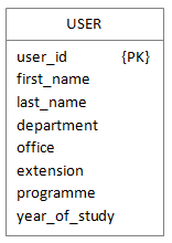
This represents a single entity type with no subclasses. This is no good if the subclasses are not disjoint or if there are relationships between the subclasses and the other entities. In addition, there will be many null fields if the subclasses do not overlap a lot. However, it avoids any joins to get additional information about each member of staff.