ER diagrams
The diagramming conventions that we are using are in fact a simple version of the class diagram defined in the Universal Modelling Language (UML) standard toolset. Although there are some differences between object-oriented modelling and relational modelling, the diagram conventions can be applied in both situations. This is convenient because you are likely to use other diagrams from UML in other modules. However, you should be aware that there are other conventions for setting out ER diagrams which use different symbols.
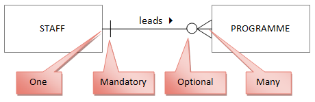
Crow's feet notation uses single or multiple ends on a relationship line to represent cardinality:
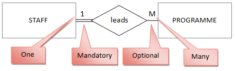
One of the first people to formulate a set of conventions for ER diagrams was P. P. Chen in 1976. His diagram placed the relationship name in a diamond, and used different types of line:
Notice that the different diagram styles convey the same essential information. Another benefit of using the UML class diagram is that it allows you to be very specific about the multiplicity of a relationship. For more information about alternative diagrams, see Connolly and Begg, or simply spend some time on the Web.
Developing an ER diagram The starting point for any database development is to extract information about the real world situation, usually through direct observation and speaking to the people involved (the eventual users of your system). If you are lucky, an analyst may already have started the process, and there may be a structured requirements specification document available. In this case, it is best to approach the spec with some scepticism: writing something down in words is a lot easier than constructing a formal consistent model, and it is highly likely that there are details missing. In a real project, you would document any assumptions that you are making in the rest of your analysis where certain information has not been provided.
As you got through the available information, try to follow the process below. Like all analysis and design processes, it is unlikely that your first pass through the steps will give an accurate result, and you will need to iterate. The process is complete when you find no more changes are required.
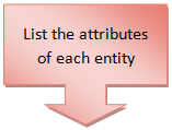
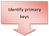
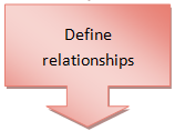
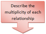
This process is generally known as entity-relationship modelling. Notice that it is a top-down process: you start from an overall idea of what you are trying to achieve, and work down through the various levels of detail.