ERD
Before creating a schema using DDL, you should have an accurate ERD which describes the relationships between tables. If you are provided with a schema description, that is an easy task: you simply transfer the information in the text description into diagram form. When you have created the schema, you can use the tools available to cross check your database with the original ERD to make sure you have not made any errors.
Using the schema description
You have been provided with the schema description shown below. Use this information to create your own ERD using the UML conventions that you have learned in the module. You should do this on paper and show it to the tutor for feedback.
sighting (sighting_id, observer_id, species_id, sighting_date, sighting_notes, region_id)
observer (observer_id, observer_fname, observer_sname)
genus (genus, family)
species (species_id, genus, species, common_name )
country (country_id, country, continent) region (region_id, region, country_id)
In constructing your diagram, follow these guidelines:
- Every table must have a primary key (underlined)
- Tables with no foreign keys (italic) can be added to the diagram straight away - let's call these tables group A
- Every foreign key matches the primary key in another table
- Foreign keys are always at the many end of the relationship
- Tables that are related to ones in group A by a single foreign key relationship can be added next
- As you add each new table, add the relationship line at the same time
- After adding each relationship line, add multiplicity labels straight away. Multiplicity information is not provided by the schema description, but you should make sensible choices
- Add any remaining tables (those with more than one foreign key)
Check your structure in SQL Developer
SQL Developer provides tools which allow you to produce diagrams of logical and relational structures. Anyone interested in developing their knowledge of Oracle tools may be interested in following up on the use of the integrated SQL Data Modeller; however, the detailed operation of SQL Data Modeller is outside the scope of this module. The following steps explain how to produce an ERD from a database schema using the two tables in the SPECIES schema as an example.
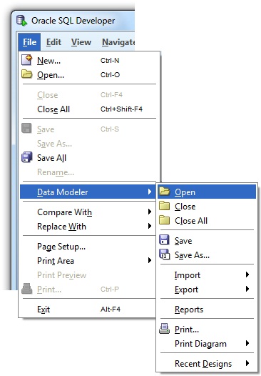
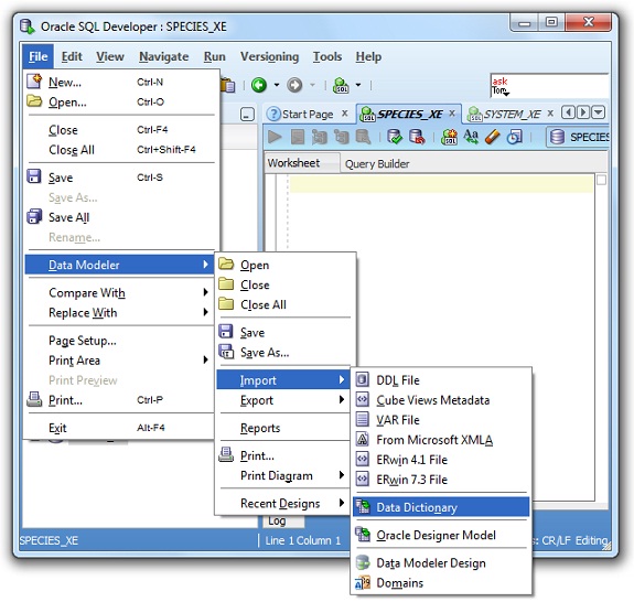
Data Modeller provides a number of ways in which to import the data required to build a diagram. In this case we will be importing directly from an existing database schema. To achieve this, choose the Data Dictionary option from the Import menu as shown below.
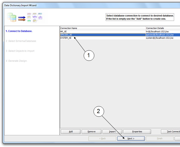
In the first step of the import wizard. select the SPECIES_XE connection as shown below (1) and click Next (2).
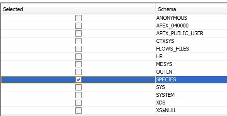
In the second step, select the SPECIES schema as shown and click Next.
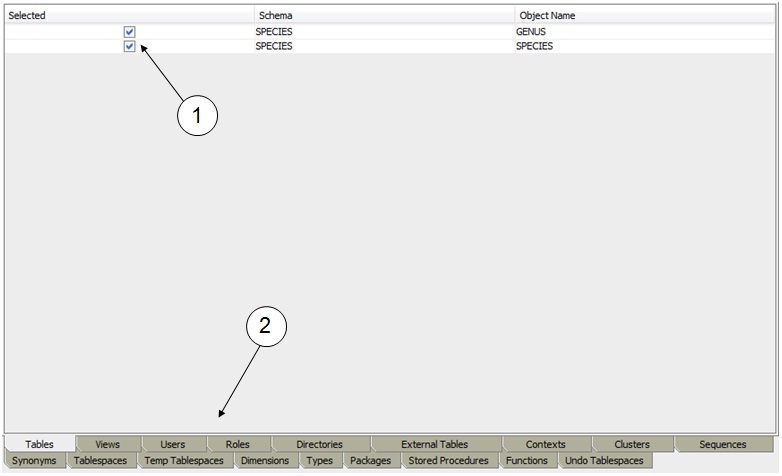
In step 3, make sure that all the tables are selected as shown below (1). Notice that this step also allows you to select other types of database object to import (2). In this case, there are no other objects, so you can immediately click Next.
The last step of the wizard is a confirmation. Here, just click Finish, and you will see a diagram like the one below created in a new tab (1):
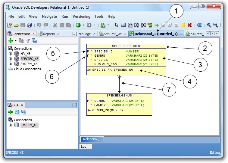
The conventions used for ERDs in SQL Developer are slightly different to those we have been using, and some explanation will help to make sense of them. Each table is represented by a yellow rectangle with three horizontal divisions. The top section (2) shows the name of the table prefixed by the name of the schema. The middle section (3) shows the definitions of the columns in the table. The bottom section (4) shows the definition of the primary key. The columns which make up the primary key are also indicated in the middle section by a P (5). Likewise, foreign key columns are labelled with an F (6). Finally, the relationship between the tables is shown as a line with different symbols at each end (7). These symbols carry most of the same information as the multiplicity labels in UML. The main feature is that the end of the relationship connecting to the parent table (the one end) has a single branch while the line connecting to the child table (the many end) has three branches.
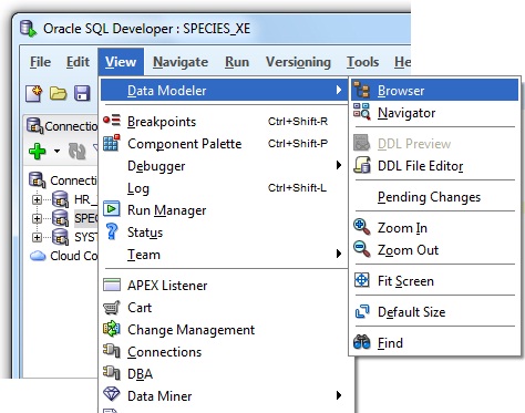
If you close the tab containing the diagram, you will not be prompted to save it. This is because the diagram forms part of a design that is held in an internal repository until you opt to save the whole thing. You can retrieve the diagram later by opening the SQL Data Modeller browser as shown below.
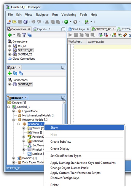
This will display a new explorer pane on the left hand side of the window. Expand the untitled design as shown below, right-click the model Relational_1 and choose Show from the pop-up menu.
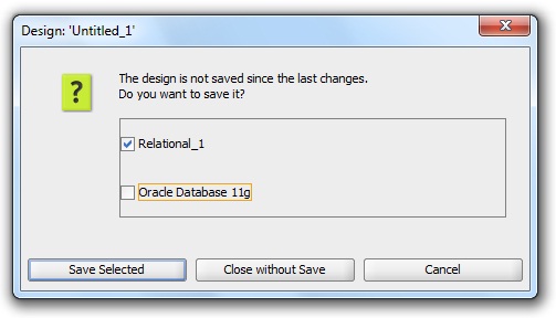
You can close the design by right-clicking on the top-level item (Untitled_1) and choosing Close Design from the pop-up menu. You will be prompted to save the model. The dialog gives you the opportunity to save some system data along with the schema objects. This is not usually necessary, so you can uncheck the Oracle Database 11g option as shown below.
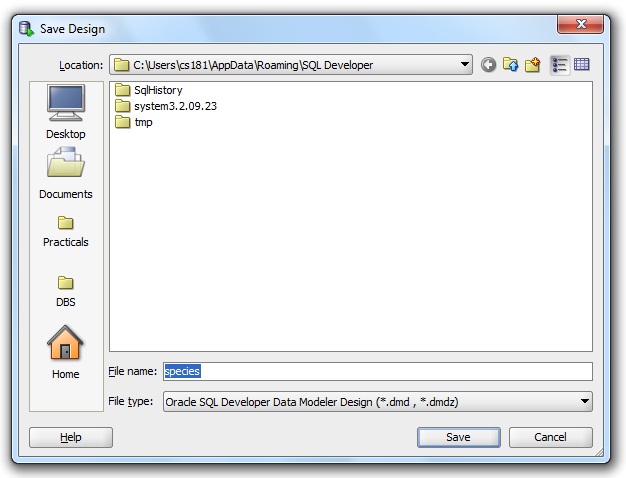
Clicking Save Selected will prompt you for a file name for the saved design. If you want to be able to retrieve the model after restarting SQL Developer you can use the name species for the file as shown below and accept the default directory.
To open a saved design, you will need to use the File menu as shown below.