Ohm's law
Voltage, current and resistance are the three basic concepts in the field of electronics that are relevant to work with the type of components we are working with. A simple way to think about them is by analogy with the way water behaves. Imagine a tank full of water that has a drainage pipe attached as shown in Figure 1.
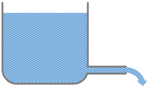 Figure 1: Water as an analogy for electricity
The depth of water in the tank creates pressure at the outlet. This is the equivalent of voltage which describes the difference in electrical potential between two points. Because of the pressure, water flows along the outlet pipe at a particular rate. This is equivalent to the electrical current in which electrons flow along a conductor such as a copper wire. The flow of water can be restricted by using a narrower pipe which puts up a greater resistance to the flow. Electrical resistance works in a similar way: materials such as copper have a low resistance and electricity flow easily through them. Other materials put up a greater resistance to the flow of electrons, and the current is therefore restricted.
Beyond these simple parallels between water and electricity, the analogy starts to break down. Nevertheless it is a useful mental image to use when thinking about simple direct current circuits and components.
Voltage, current and resistance are related by Ohm's law:
where V is voltage, I is current and R is resistance.
Units and symbols
Voltage is measured in volts (V)
Current is measured in amperes or amps for short (A)
Resistance is measured in Ohms (Ω)
The simplicity of Ohm's law makes it very easy to apply. It is a simple linear relationship among only three quantities, and in many situations, one or two of those may be fixed. Where two of the quantities are known, the third can be calculated by Ohm's law. For example, an LED is a sensitive device with virtually no resistance. Components are described by their electrical characteristics, and in the case of LEDs an important value is the the current rating. This figure specifies the maximum current that the LED can tolerate before it is damaged, and is usually around 20 mA (0.02A).
Imagine that we want to connect an LED directly to a 9V battery. We know the voltage from the rating of the battery, and we also know that the LED has almost no resistance. We can calculate the expected current using Ohm's law:
Substituting 5 for V and zero for R gives a division by zero suggesting an infinite current. In practice of course it is limited by the characteristics of the battery, but it is nevertheless probably enough to explode the LED. A resistor could be placed in series with the LED to limit the current - the question is how large the resistance value should be. We can use Ohm's law again to work out the optimum value using the rated current of the LED:
Substituting:
Therefore we need a resistor or 450Ω or more to protect our LED.
As an exercise, work out the minimum resistance needed to protect an LED when it is powered by the 5V output from an Arduino prototyping board.
 Further reading