Gyroscopes
Large scale gyroscopes consist of a spinning disk supported by a gimbal. This jointed frame allows the disk and its support to rotate independently of each other. The motion of the disk produces forces that cause the disk to behave in unintuitive ways that seem to defy gravity. The video linked in the box on the right provides an intuitive explanation for why this is.
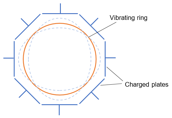
Gyroscopes tend to resist attempts to change their orientation. So, when the supporting structure rotates, the spinning disk will remain in its original orientation and the difference between them can be measured. Instead of a spinning disk, the gyroscopes in mobile phones have vibrating components which have similar properties to spinning ones in that they also resist changes in orientation. The figure below shows how a Micro-Electro-Mechanical (MEMS) gyroscope is formed from a vibrating ring surrounded by conducting plates. If the housing of the MEMS gyroscope changes, the apparent vibration of the ring will no longer be up/down and side-to-side as shown; it will appear to have been rotated slightly. Just as in an accelerometer, the changes in distance between the ring and the plates cause changes in capacitance which can be measured.
The second video in the box explains a little more about MEMS devices including the accelerometer and the gyroscope. It also provides some explanations of how to use MEMS devices with Arduino boards so that the movements of the system can be tracked.
 MEMS gyroscope
A vibrating ring at rest and rotating
 Gyroscopes explained