Skip to content

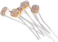
A photoresistor light detector

Photosensitive resistors

This exercise introduces analogue signal acquisition. In analogue sensing applications - light, temperature, pressure, gas, alcohol, proximity, etc - changes in a physical quantity are converted to voltage changes and interfaced to a microcontroller (MCU) using an analogue-to-digital Converter (ADC). Since the ADC sampled value is proportional to sensed quantity it is a straightforward matter to acquire information about all manner of conditions in the local environment. The front-end of the Internet-of-Things (IoT) will require millions of sensors, actuators and MCUs

A photoresistor, as its name suggests, changes its electrical resistance as the light falling upon it changes - resistance decreases as light increases. The resistance changes smoothly through the range of possible values rather than changing in steps. This is the nature of analogue signals - they are infinitely divisible. The Arduino provide special pins for reading analogue values - refer back to the notes if you don't remember where they are.

Set up the circuit below to take the first steps into analogue signal processing.

Copy and upload the code below. Once it is running, open the serial monitor to see the readings from the photoresistor.

 1
 2
 3
 4
 5
 6
 7
 8
 9
10
11
12
13
14
15
16
17
18
19
20
21
    const int PhotoCell  = A0;                   // Select the input pin for the PhotoCell

    const int TLed = 13;                         // Onboard LED
    unsigned int photoval;

    void setup(){
      pinMode(TLed, OUTPUT);
      Serial.begin(9600);
    }

    void loop()
    {
      digitalWrite(TLed,HIGH);                   // Turn ON onboard LED to show activity

      photoval = analogRead(PhotoCell);          // Read Photocell
      Serial.print(" Photocell Reading  >> ");
      Serial.println(photoval);                  // A blank line to clarify the monitor display

      digitalWrite(TLed, LOW);                   // Turn OFF onboard LED to show one cycle is complete
      delay(200);
    }

The Arduino coding language provides a way of reading analogue values too. The analogWrite() command uses a technique called pulse-width modulation (PWM) to simulate an analogue output on a digital pin (mode of PWM later). Theoretically, then, we should be able to pass the value from the photoresistor to an LED so that the LED is bright in bright light and dim in low light.

Modify your circuit to match the one shown below.

There is a problem however. You may have noticed that the values being read from the photoresistor range between 0 and 1000. This does not match the range offered by the analogWrite() function whose input ranges from 0 to 255. To overcome this mistmatch, we can use the map() function. There is an example in the code below and you can get an explanation from the Arduino language reference page using the link on the right.

 1
 2
 3
 4
 5
 6
 7
 8
 9
10
11
12
13
14
15
16
17
18
19
20
21
22
23
24
    const int PhotoCell = A0;                   // Select the input pin for the PhotoCell
    const int REDLed    = 7;                    // Pin for LED

    unsigned int photoval;
    unsigned int ledval;

    void setup(){
      pinMode(REDLed, OUTPUT);
      digitalWrite(REDLed, LOW);                // Make sure that the LED is initially OFF
      Serial.begin(9600);
    }

    void loop()
    {
      photoval = analogRead(PhotoCell);          // Read Photocell
      ledval = map(photoval, 0, 1000, 0, 255);   // Map the sensor range to the actuator range
      Serial.print(" Photocell Reading  >> ");
      Serial.print(photoval);
      Serial.print(" => ");
      Serial.println(ledval);

      analogWrite(REDLed, ledval);               // Write modified value to the LED
      delay(200);
    }

An analogue signal can also be used to drive an RGB LED - that's one which effectively changes colour depending on the inputs it is given. Using the circuit below, we can make the RGB LED change colour according to the ambient brightness. When the light levels are low, the LED will be red and as the light increases it will move through yellow, green, turquoise and finally blue.

Copy and upload the code below to see your analogue-to-analogue system operating.

 1
 2
 3
 4
 5
 6
 7
 8
 9
10
11
12
13
14
15
16
17
18
19
20
21
22
23
24
25
26
27
28
29
30
31
32
33
34
35
36
37
38
39
40
41
42
43
    const int PhotoCell = A5;                   // Select the input pin for the PhotoCell
    const int REDLed    = 11;                   // Pins for RGB LED
    const int GREENLed  = 10;                   // Pins for RGB LED
    const int BLUELed   = 9;                    // Pins for RGB LED

    unsigned int photoval;
    unsigned int redval;
    unsigned int blueval;
    unsigned int greenval;

    void setup(){
      pinMode(REDLed, OUTPUT);
      digitalWrite(REDLed, LOW);                // Make sure that the LED is initially OFF
      digitalWrite(GREENLed, LOW);              // Make sure that the LED is initially OFF
      digitalWrite(BLUELed, LOW);               // Make sure that the LED is initially OFF
      Serial.begin(9600);
    }

    void loop()
    {
      photoval = analogRead(PhotoCell);          // Read Photocell
      redval = map(photoval, 0, 1000, 0, 255);   // Map the sensor range to the actuator range
      if (photoval < 450) redval = map(photoval, 0, 449, 0, 255);
      if (photoval >= 300 && photoval < 700) greenval = map(photoval, 300, 699, 0, 255);
      if (photoval >= 600) blueval = map(photoval, 600, 1000, 0, 255);

      Serial.print(" Photocell Reading  >> ");
      Serial.print(photoval);
      Serial.print(" => ");
      Serial.println(redval);
      Serial.print(", ");
      Serial.println(greenval);
      Serial.print(", ");
      Serial.println(blueval);

      digitalWrite(REDLed, LOW);
      digitalWrite(GREENLed, LOW);
      digitalWrite(BLUELed, LOW);
      analogWrite(REDLed, redval);
      analogWrite(GREENLed, greenval);
      analogWrite(BLUELed, blueval);
      delay(200);
    }

You will probably find that the colours do not behave as you expect. You will need to experiment with the numbers used in the calls to the map() function to improve the system.

There is some repetition in the final code example. You could improve it by introducing some functions. Find out how to do this on the Arduino Web site.

Further reading

Map function reference analogWrite()

Map function reference map()