RFID
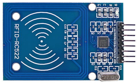 Figure 1: RC522 RFID module
This module, which usually comes with a programmable card and fob, can be used to read information from an RFID tag, and also write information to a tag. It uses the SPI communication method which is a standard method for connecting many serial devices using a small number of wires. The table below summarises the four standard SPI connections.
| Code | Meaning | Comment |
|---|---|---|
| SCLK | Clock | All types of serial communications require a time reference to coordinate the signals between the sending and receiving devices |
| SSn | Slave select | In SPI, each connected device is activated with a high signal on this wire to allow it to communicate with the master device |
| MOSI | Master Out, Slave In | Signals from the Argon (Master) to the RC522 (Slave) |
| MISO | Master In, Slave Out | Signals from the RC522 (Slave) to the Argon (Master) |
Hardware connections
The Argon includes a hardware interface for SPI, and also allows for additional SPI connections in software. This makes it very flexible, but can be confusing when trying to interpret the pin-out diagram in Figure 2.
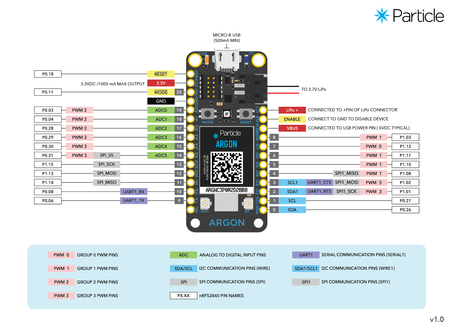 Figure 2: Argon pin-out diagram
To connect the RC522, we need to use the built-in hardware interface which corresponds
to pins 11 - 14 on the left side of the diagram. Even this is not perfectly accurate,
however, since in the code example below, the SSn connection is configurable and
does not use Argon pin 14 as you might expect.
The RC522 has eight pins in all and does not always use the standard codes as shown above. The next table explains the pins on the module matching them up to the standard SPI functions where appropriate, and also shows which pins they should be connected to on the Argon. The colour refers to the connections in Figure 3.
| RC522 pin | SPI function | Argon pin | Colour | Comment |
|---|---|---|---|---|
| SDA | SSn | Configurable | Orange | Use pin D07 in the example below |
| SCK | SCLK | SPI_SCK (13) | Yellow | |
| MOSI | MOSI | SPI_MOSI (12) | Green | |
| MISO | MISO | SPI_MISO (11) | Blue | |
| IRQ | - | - | - | Used for interrupt-driven programming - see below |
| GND | - | GND | Black | Ground connection |
| RST | - | Configurable | White | Used to reset the RC522 board. Use Argon pin D07 in thre example below. |
| 3.3V | - | 3.3V | Red | Input power |
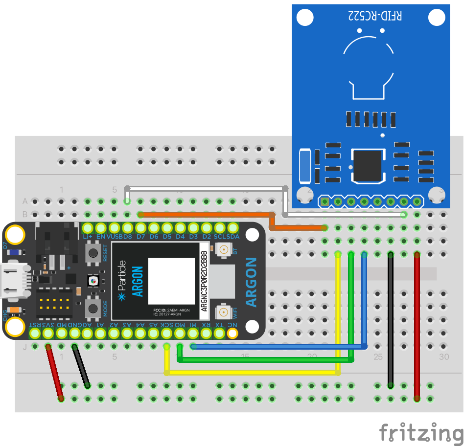 Figure 3: Breadboard layout
Software
The Particle IDE gives access to several libraries for working with RFID modules, and each one comes with some example sketches. As is often the case, the libraries and examples have been adapted from code originally written for the Arduino family of processor boards. In this particular instance, some minor details have been overlooked and you will need to fix them
First, search for rfid in the Particle IDE. This should retrieve several options
as shown in Figure 4. You should choose ARGON-RFID-MFRC522.
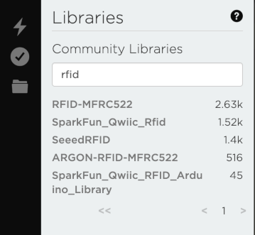 Figure 4: RFID library search
Once the library is selected, the sidebar will display a set of example sketches (you
may need to scroll down to see them). Select the example called ReadAndWrite.ino and
click the button labelled Use this example. This will create a copy of the example on
your computer that you can modify.
The issue with the code is that it references microprocessor that exist on an Arduino board but not on a Particle Argon. The fix is simply to alter the code to use different pins.
1 2 3 4 5 6 7 8 9 10 11 12 13 14 15 16 17 18 19 20 21 22 23 24 25 26 27 28 29 30 31 32 33 34 | |
The code above comes straight from the example. You can see that the assumption is that you are using one of the Arduino boards mentioned in the comments.
Lines 33 and 34 contain the pin configurations for the SDA and RST connections.
Because the Argon only provides eight digital pins, these assignments will not
work. Change the RST_PIN value to 8 and the SS_PIN value to 7. These values
correspond to the connections shown in Figure 3. With these changes, you should now
be able to upload the sketch to your Argon.
Because it is designed as a demonstration, the code includes some messages that are written to the serial port. To view them, start a Particle CLI session and type ther command
1 | |
Some of the messages are produced by the setup() function. That means they only
appear when the board is reset. If you start the serial monitor before the Argon
has connected to WiFi, you will see these messages with no problems. If you start
the serial monitor after WiFi connection, you will have missed them. You can reset
the board either by unplugging the USB cable, or pressing the on-board reset button.
Either way, remember to start the serial monitor while the Argon is connecting to WiFi
so that you do not miss the first few messages.
To understand what the example sketch is doing, you can use the serial messages and the comments in the code. Once you know how it works, you can start to modify it for your own purposes. If you think that a different example would make a better starting point, just follow a similar process to get it going.
Interrupt-driven processing
Usually, sensors are checked for input every time the loop() function runs. This is
OK in many situations, such as when you want to monitor an environmental variable like
temperature on a regular basis. To control the frequency of the sensor readings, it
is common to introduce a delay into the loop() function using the delay() function.
For something like a card read, though, this is not efficient. It means that the majority
of the time, the processor is doing a lot of work for nothing because no RFID tag is
present. It is also possible that someone will present their card for reading during the
delay. It such a case, the reading will not happen.
An alternative approach that captures events when they happen is to use a signal from the sensor to wake up the board and trigger the required processing. A signal used in this way is called an interrupt because it pauses any processing that is currently underway in order to process the incoming signal. Once that processing is complete, the board goes back to whatever it was doing before.
A complete explanation of interrupt-driven processing is not yet covered in these notes,
but if you are interested in following this up, you could experiment with the example,
MinimalInterrupt.ino provided with the library.
 Fritzing part