Pulse width modulation
The signals that can be generated on the digital pins of an Arduino prototyping board are very simple to use but also very limited. They only have two states, on/high or low/off. This is fine for many applications, but some situations require greater variation. For example, it might be necessary to control the brightness of an LED or the orientation of a servo motor. To do that requires a voltage somewhere between zero and 5. This is where the technique of pulse width modulation (PWM) can be used. Essentially it involves switching the 5V signal on and off at a known rate so that the average voltage corresponds to the desired value.
Switching the signal on and off creates a square wave form such as those shown in Figure 1. The proportion of time that the signal is on compared to the proportion of time that it is off is known as the duty cycle and it is measured in percent. When the signal is averaged over time, the effective voltage is equal to the full voltage multiplied by the duty cycle.
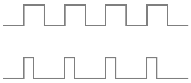 Figure 1: Pulse width modulation 50% duty cycle (top) and 25% duty cycle (bottom)
As well as producing a steady voltage lower than the voltage of the signal, PWM can also be used to emulate sine waves. This can be useful for controlling audio devices such as simple piezo speakers, and the same technique if used in a device called an inverter to convert direct current electricity into alternating current. The principle is the same but instead of a series of evenly-spaced pulses of equal duration, the width and separation of the pulses is manipulated to create the required output.
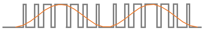
Figure 2: Sine wave emulation using PWM
PWM on the Arduino Uno
The Arduino language makes the use of PWM almost trivial by providing the
analogWrite() command. This automatically
generates a modulated signal on a digital pin. The command takes
parameters in the range 0 - 255 where 255 represents a 100% duty cycle,
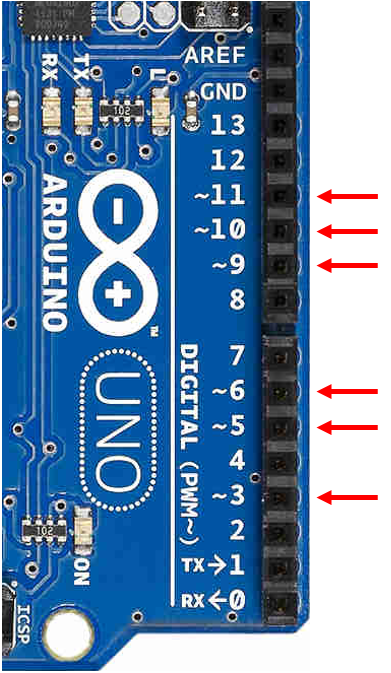
127 represents 50%, etc. The choice of digital pin is important because
they are not all capable of PWM. Those that are capable are labeled with a
tilde next to the pin number.
 Further reading