Voltage management
All electronic components have electrical limits which must not be exceeded. Failure to observe these constraints can cause damage and in some cases, excessive heating which can become dangerous. When connecting devices to form a circuit, you should always check the maximum voltage and current that each device can tolerate.
Sometimes, there may be a voltage mismatch between two devices. For example, an Arduino microprocessor uses 5V as standard but many other components such as Bluetooth modems use 3.3V. In that situation, you need a method for stepping the 5V signals from the Arduino down to 3.3V to prevent damage to the modem. This can be done using a voltage divider or a voltage regulator.
Another situation where voltages are important is where you want to control a device such as a 5V sensor using a 3.3V processor such as a Particle Argon. In that case, you cannot step the processor's low voltage up. Instead, you need to use a second power supply. Where two power sources are used, unpredictable behaviour can occur unless they share a common reference. This can be ensured by connecting their negative sides together to form a common ground. If the second power supply is larger than that required by the sensor, then you may also need to use a voltage regulator. A similar situation occurs if you want to drive a motor using a low-voltage processor.
Voltage management is also important when you want to use a sensor whose resistance changes in response to the external conditions. This is the case, for example, with a light-dependent resistor. The analog pins on a microprocessor are sensitive to voltage changes, but not to changes in resistance. You can use a voltage divider to convert the changes in resistance to changes in voltage.
Voltage regulator
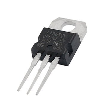 A voltage regulator may be used where
you need a stable voltage which is lower
than that supplied by your power source. The voltage regulator also smooths out
any variations in the power supply. It is a single device with three pins, input
voltage, ground and output voltage. Voltage regulators are specified by their
output voltage, but they also have a maximum input voltage limit which must not
be exceeded.
A voltage regulator may be used where
you need a stable voltage which is lower
than that supplied by your power source. The voltage regulator also smooths out
any variations in the power supply. It is a single device with three pins, input
voltage, ground and output voltage. Voltage regulators are specified by their
output voltage, but they also have a maximum input voltage limit which must not
be exceeded.
Microprocessor boards have on-board voltage regulators to control the input voltage. This allows them to use power sources such as batteries which have a higher voltage than the actual microprocessor. The voltage regulator ensures that the microprocessor receives a reliable, steady voltage until the battery is depleted past a low threshold.
Voltage divider
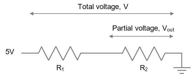
When two resistors are arranged in series with a positive voltage at one side and ground at the other, the voltage drop across both resistors is equal to the value of the positive voltage. However, the voltage actually drops in two steps, one for each resistor. The voltage measured between the two resistors depends on the value of the positive voltage and the ratio of the two resistance values according to the equation below.
Where V is the total voltage and Vout is the partial voltage measured as shown below over R2.
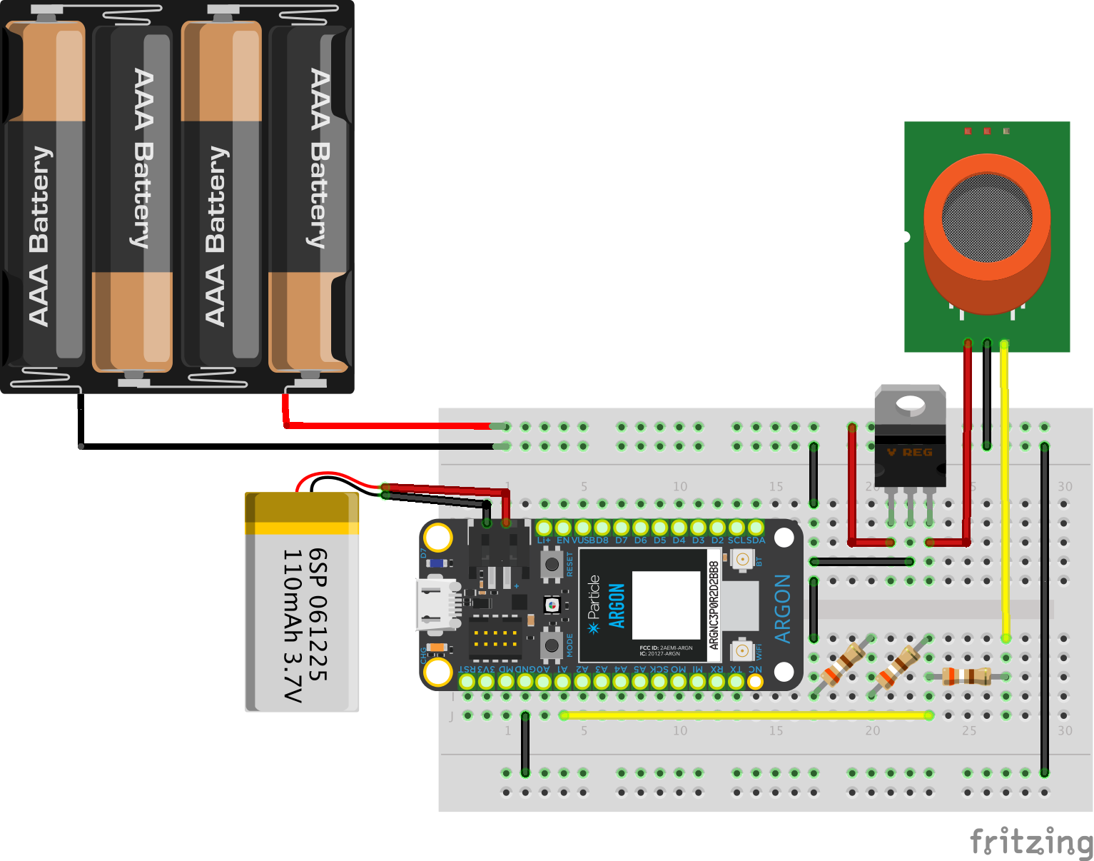
A voltage divider can be used, for example, to step a signal voltage from a 5V device down so that it does not damage a connected 3.3V device. The circuit below shows a 3.3V Particle Argon microprocessor receiving signals from a 5V gas sensor. The sensor requires a second power source to provide the 5V it needs. The signal from the sensor passes through a voltage divider made up of three resistors of identical value before being read on one of the Argon's analogue pins.
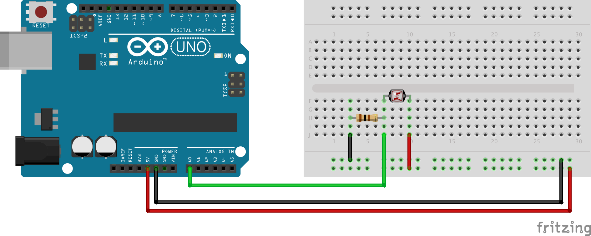
A similar arrangement can be used to read a value from a sensor whose resistance varies according to the quantity of interest. A light-dependent resistor (LDR), for example, reacts to the ambient light level. To turn the change in resistance into a change in voltage that can be read by a microprocessor, the LDR is combined with a fixed resistor and the voltage between them is measured. This is shown in the circuit below.
Common ground
A voltage exists between two points when there is a difference of electrical potential between them. This means that if they are connected together, an electric current will flow between them until their electrical potential is equal. Voltage is also known as potential difference for this reason. Understanding voltage in this way shows that it is actually a relative quantity. This can have and impact on electrical circuits with more than one voltage source: as well as the expected potential differences, there may be an unexpected potential difference between their grounds (eg the negative poles of batteries). To eliminate these unwanted differences, the two voltage sources need a common frame of reference. This can be achieved simply by connecting their grounds together. There is an example of this in the gas sensor diagram above. The ground pin of the microprocessor is connected to the lower breadboard rail. The black wire on the far right of the layout connects the lower rail to the top one where the 4 x AA battery pack is connected. Note that the positive terminals are not connected: that would defeat the purpose of having two separate power sources, and would lead to unpredictable and possibly damaging consequences.
 Ground explained
 Voltage dividers