Motor driver circuit version 2
In building the example circuit you should have gained some understanding of its structure and how the components are connected. We will now make use of that new knowledge in order to free up the larger breadboard for future work.
This section of the exercise requires you to transfer the circuit you have created onto the smaller blue breadboard.
Arduinos and breadboards are designed to make it easy to prototype electronic circuits and systems. In a real final product, the bulky through-hole components would probably be replaced by surface-mounted components soldered onto a bespoke printed circuit board (PCB).
In this step, you are making the first move towards optimising the layout of your circuit so that it could eventually be turned into a compact independent component. You can think of this process as equivalent to refactoring a piece of code: it is an opportunity to resolve some of the less-than-perfect details that crept in while you were developing the first version.
To carry out the transfer effectively, you will need to have a clear understanding of the example circuit and the components. Take a moment, for example, to think about the connections on your H-bridge and what the most efficient way of laying them out will be. A diagram will help with this and you can create one either with Fritzing, or using the online service at tinkercad.com.
You may need to make up some short jumper wires to keep your new circuit tidy. Resources are available for you to do this. The figure below is taken from the datasheet for an SN75440 quadruple half H-bridge motor driver. Searching for the full pdf datasheet online will provide more information.
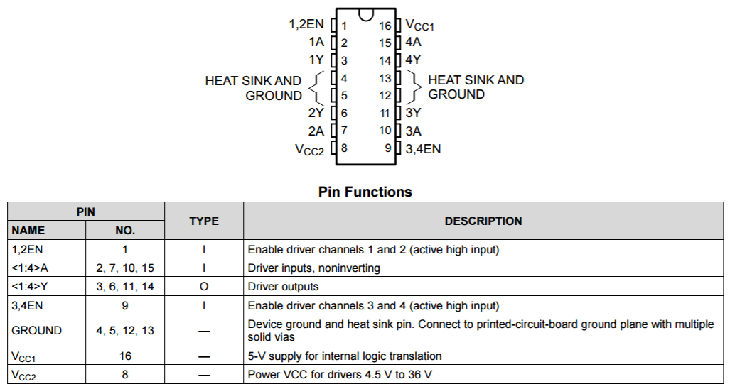 H-bridge pin-out
 PCB
PCB Fritzing
 Tinkercad