Ultrasonic rangefinder
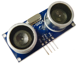 Figure 1: HC-SR04 ultrasonic range finder
The HC-SR04 ultrasonic range finder is designed to work on 5V which is standard for the Arduino family of prototyping boards. However, the Particle Photon2 works on 3.3V and some care needs to be exercised when using the two together. There are actually two separate issues - the first is how to supply 5V to the HC-SR04, and the second is how to prevent the Photon2 being damaged if the HC-SR04 sends a 5V signal on the echo pin.
If your Photon2 is running connected to a computer or to a power outlet over
USB, you can take 5V from the VUSB pin. To solve the second problem and
protect the Photon2, you can use a voltage divider to step the 5V signal
down to 3.3V. Figure 2 shows how to set up the connections on the
breadboard using three 1 kΩ resistors. Connecting the signal pin
between the first and second resistors gives 1 kΩ on one side and
2 kΩ on the other.
It is not vital to use exactly these values as long as one resistor is twice the rating of the other. Also, remember that you can connect resistors in series and their total resistance is the sum of the individual resistances.
 Figure 2: Breadboard layout
Next, go to the libraries tab in the Particle Web IDE and search for HC-SR04. You will find that there is some example code ready to go. Please check which pins are used for trigger and echo in the example sketch that you use. Fig. 2 shows D4 used for trigger and D5 used for ground. If your sketch uses different pins you can either change the code or the pin connections, but they must match.
 Particle console
 HC-SR04 for Arduino