Coordinates
If you want to tell the computer to draw something on the screen, you need to tell it where to start and where to stop. It is therefore necessary to have a way of describing the screen area using numbers. This is known as a coordinate system. In Processing, the top left-hand corner of the screen area is known as the origin. From that point, positions on the screen are described by a pair of numbers. The first represents the horizontal position (the x-direction), and the second represents the vertical position (the y-direction). The position at the origin is zero in both directions which is written (0,0).
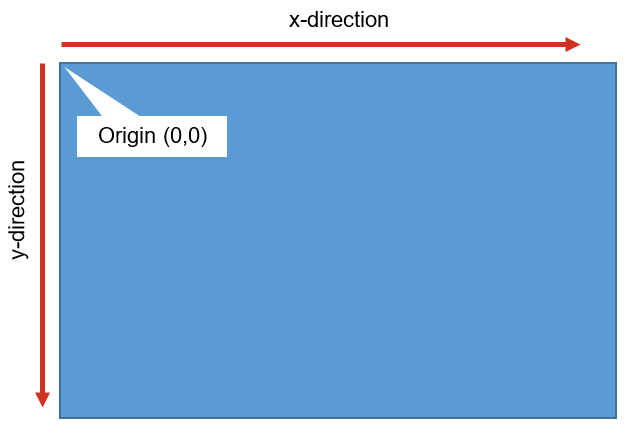 Figure 1: Processing's coordinate system
Getting started
The best way to understand how Processing works is to start coding straight away. Let's draw a line!
Open the Processing development environment (PDE) and you will see an area where you can write your code. Figure 2 shows the main elements. It also illustrates the main structure of a Processing sketch.
The setup() function runs once when the
sketch first starts. Its purpose is to initialise any variables and
perform any other actions needed to configure the context of the sketch.
The draw() function repeats continuously
while the sketch is running. This provides a natural way to perform
animations.
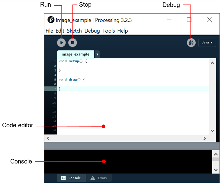 Figure 2: The Processing IDE
The code in the box below draws a line on the screen starting at the point (150,25) and finishing at the point (270,350). Copy it into a new sketch window in Processing, click the Play button and see what happens.
1 2 3 4 | |
Here is an explanation of the code line by line:
| Line | Command | Description |
|---|---|---|
| 1 | size(400, 400); | Sets the size of the image window. As well as expressing the size as x and y coordinates, you can also say fullScreen() |
| 2 | background(192, 64, 0); | Sets the colour of the image background |
| 3 | stroke(255); | Sets the colour of the line |
| 4 | line(150, 25, 270, 350); | Draws the line from (150,25) to (270,350) |
Experiment with these options a little:
- Change the size
- Change the background colour
- Use several lines to draw a simple picture such as a house
Interaction with the mouse
The reason for drawing with code is to provide interaction. The example
below defines one end of the line to be the mouse position. A line is
drawn every time the draw() function
repeats. If the mouse position changes, an interesting pattern can be
developed. Load the example into a new sketch and run it.
1 2 3 4 5 6 7 8 9 | |
Processing draws the lines on top of the background. If you move the
background() function from setup() to draw(), the images starts again every
time draw() repeats. The effect is that
there appears to be one line which follows the mouse rather than a whole
series of lines. Try it.
You can use the mouse position coordinates in other ways too. For
example, try setting using them as the parameters to the background()
function.
Processing can also react when the user presses the mouse button. In the following example, pressing the button refreshes the background.
1 2 3 4 5 6 7 8 9 10 11 12 | |
Saving your work
You can save your work in two main ways - as a working application, or as a static image file. Either way, you must save the sketch first so that the sketch folder is created. To save it as an application, choose File → Export Application... from the menu. You will find that an executable file is created in the sketch directory.
To save it as an image, you need to use the
saveFrame() function in your code. Be Careful !
If you put this command into the draw()
function it will save a new file every time the
draw() function repeats! The example below offers a safer option
by saving a file only when the user clicks the mouse button.
1 2 3 4 5 6 7 8 9 10 11 12 13 | |
In this code, the saveFrame() command
always overwrites the same file. That way, you will avoid creating
hundreds of unwanted files in the sketch directory.
The example also demonstrates the use of the delay() function. Here it
is used to insert a delay of 100ms between repeats of the draw()
function. The result is a series of lines that are more widely spaced.
Two dimensional shapes
As well as lines, Processing lets you draw simple shapes such as ellipses and rectangles. By setting the dimensions carefully, you can also produce circles and squares. The following example places a small circle in the middle of the image.
1 2 3 4 5 6 7 | |
Things to notice:
-
The
ellipse()function takes four parameters. The first two specify the centre of the shape, and the last two are the width and height. You can find information about functions and their parameters in the Processing reference material. -
The centre of the ellipse in the example is set relative to the screen size.
-
You can control the colour of the stroke and fill, and the weight of the stroke with special functions.
You can use the Processing reference page to find functions for drawing other types of shape.
 Processing web site