Introduction to electric motors
Electric motors come in all shapes and sizes. For the scale of project that we will be working on in this modules, however, there are only a few types that will be relevant. This section provides some information about them.
All electric motors work on the same basic principles, the main one of which is that a conductor (wire) which is placed in a magnetic field will experience a lateral force when current flows through it as illustrated in Figure 1. The direction of the force experienced by the conductor depends on the direction of the magnetic field and the direction of the current. In the figure, the magnetic field does not change. The conductor, however, passes though the magnetic field in one direction and then loops back again. The two halves of the wire loop therefore experience forces in opposite directions and this causes the motor to turn.
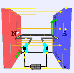 Figure 1: Schematic representation of a simple DC motor showing the interaction between the electrical current and the magnetic field by Lookang many thanks to Fu-Kwun Hwang and author of Easy Java Simulation = Francisco Esquembre (Own work) CC BY-SA 3.0, via Wikimedia Commons
The motor in Figure 1 is a brushed DC motor. In order to keep the motor turning in the same directions, the current in the wire needs to be reversed every 180° - this is the job of the commutator shown in cyan. The electrical connection with the commutator is made using steel brushes which slide along its surface as it turns.
Other types of electric motor use different strategies for generating a magnetic field and maintaining the flow of current in the required direction. At base though, they all employ the same basic principle.
Power and control
The speed of rotation of a DC motor is a function of the strength of the magnetic field, the current and the number of turns of wire that pass between the poles of the magnet. In some motor designs there are more than two magnetic poles, and this would also affect the speed of rotation. However, as long as the load on the motor remains constant, the speed of rotation is proportional to the input voltage. This is a very useful characteristic of DC motors because the voltage can be precisely controlled from an Arduino using pulse-width modulation.
When a motor first starts, it can draw up to 20 or 30 times the amount of current required in a steady running state. This inrush current can cause damage to other electrical components if it is not controlled. In small-scale applications it may be enough to protect the motors power supply with capacitors. Their job is to smooth the electrical supply which in this case would mean discharging quickly at the moment the motor starts in order to provide the additional boost of current needed. In many cases, it is also a good idea to separate the power supply for the motor from the supply for the control electronics. This is particularly true for larger motors that require considerably larger currents than microcontrollers do. We could use a transistor to do this because a transistor can switch a relatively large current with only a small control voltage; however, it is important to ensure that the transistor will stay within its rated operating limits. The link in the resources box provides more information on this topic.
An H-bridge is a component consisting of four transistors (Q1 - Q4) arranged as shown in Figure 2, and is specifically designed for controlling small DC motors. The article linked in the resources box provides an excellent description of the internal operation of an H-bridge. Different combinations of switch positions are used to drive the motor in one direction or the other.
 Figure 2: H-bridge by Modular Circuits (see link in Further reading)
The second main method for controlling large currents with smaller ones is to use a mechanical relay. These devices perform the same function as a transistor in that they close (or open) when a small control current is supplied. The difference is that since they are mechanical devices they can be constructed to withstand just about any size of current. This makes them very effective for controlling very large motors. Figure 3 shows a very simple mechanical relay: the main current to power the motor should flow from A to B. To close the circuit, enough power is supplied to the electromagnet to attract the movable arm. Using a relay, a few milliamps could be used to switch a current of tens of amps. For a larger supply current, the electrical insulation between the two circuits needs to be more effective, but in practice that just means a larger device.
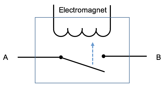 Figure 3: A simple mechanical relay
 Electric motors
 Adafruit motor selection guide
 Speed and voltage