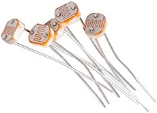
Light-dependent resistor
A light-dependent resistor (LDR or photoresistor), as its name suggests, changes its electrical resistance as the light falling upon it changes - resistance decreases as light increases. The block diagram shows a photoresistor connected to analogue input pin10 so it is a fairly easy task to determine the lighting conditions in the local environment.
Using a voltage divider
When taking a measurement from a photosensitive resistor, example circuits include a second non-variable resistor. The reason for this is that the analog pins on an Arduino are sensitive to voltage changes, but not to changes in resistance. However, when two resistors are placed in series, the total voltage is distributed between them in proportion to their values. That means that if we measure the voltage between the resistors, we get a value that depends on the ratio of the resistor values. If one of the resistances changes, so does the voltage between them. This is the purpose of a voltage divider circuit: to convert changes in resistance to changes in voltage.
The relationship between two resistors in series is shown in Figure 5.
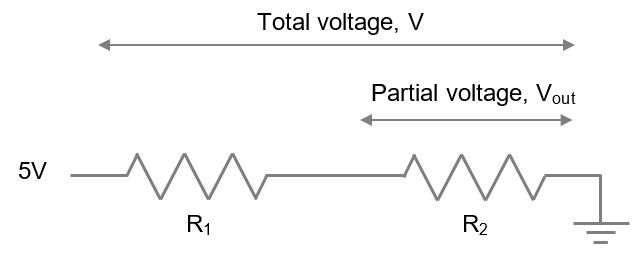
The value of the partial voltage over one resistor can be found using the equation below.
Where V is the total voltage and Vout is the partial voltage measured as shown over R2.